
Manufacturers can make production data available to every enterprise system without making the production network reachable from them. This data diode reference architecture shows how: i-flow Edge runs on the plant floor, and an ArrowLinx Data Diode from Allied Solutions sits between it and the i-flow Unified Namespace (UNS). Modeled data moves from OT to IT, and no return path exists across the boundary. The first part of this series explained why a data diode and a UNS complement each other. This second part maps the architecture onto the Purdue levels for two typical situations: plants connected directly through i-flow Edge and plants that already run Kepware. It also covers the data path, multi-plant scaling, central governance and an implementation framework in eight steps.
The Data Diode Reference Architecture at a Glance
The data diode reference architecture runs i-flow Edge at Level 3 and places one ArrowLinx Data Diode per plant in the Industrial DMZ. As a result, every byte that reaches the UNS has been modeled at the source and has crossed a hardware-enforced one-way boundary. The architecture is mapped onto the familiar Purdue levels, from the physical process (Level 0) to the enterprise network and cloud (Level 5).
Plant A on the left connects its sources directly through i-flow Edge. Plant B … n on the right keeps an existing Kepware layer, which feeds i-flow Edge. Both plants follow the same pattern from the diode upward and publish into one global i-flow UNS.
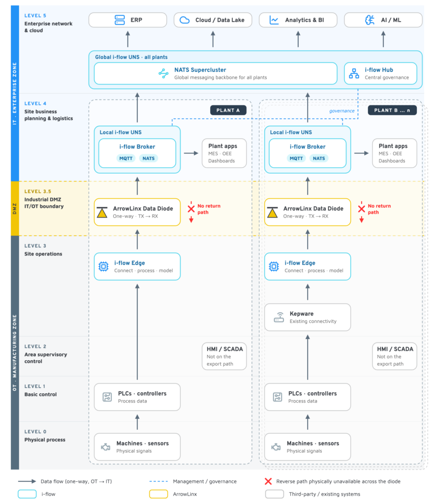
Solid arrows show one-way data flow from OT to IT. The dashed line is management and governance. The red cross marks the reverse path that is physically unavailable across the diode.
| Level | Zone | Components | Role in the architecture |
|---|---|---|---|
| 5 · Enterprise network & cloud | IT | Global i-flow UNS: i-flow Hub for central governance and a NATS Supercluster as global messaging backbone; ERP, cloud / data lake, analytics & BI, AI/ML | All plants publish into the NATS Supercluster; enterprise systems subscribe to it |
| 4 · Site business planning & logistics | IT | Local i-flow UNS (i-flow Broker on MQTT and NATS); plant apps: MES, dashboards, quality, OEE | Plant UNS receives modeled data from the diode and serves site applications |
| 3.5 · Industrial DMZ | IT/OT boundary | ArrowLinx Data Diode: TX send side (OT), RX receive side (IT) | Hardware-enforced one-way transfer; no return path |
| 3 · Site operations | OT | i-flow Edge: connect, process, harmonize; optionally fed by an existing Kepware layer | Turns raw machine data into UNS-ready information and hands it to the diode |
| 2 · Area supervisory control | OT | HMI / SCADA | Continues to run plant operations; not on the export path |
| 1 · Basic control | OT | PLCs and controllers | Source of process and machine data |
| 0 · Physical process | OT | Machines, sensors, actuators | Generate the underlying signals |
From the Source to the UNS: the Data Path
Data travels upward through six stages and never needs to travel back down. Each stage has one owner, so a failure or a change is easy to locate. The stages are identical in every plant of the data diode reference architecture:
- Generate: Machines, sensors and actuators (Level 0) feed PLCs and controllers (Level 1).
- Connect and model at the source: i-flow Edge (Level 3) connects to the required sources, either directly or through an existing Kepware layer. It processes and harmonizes the data and models it into the UNS structure.
- Cross the boundary: Only the required outbound stream enters the ArrowLinx TX side (OT), crosses the diode one way and leaves the RX side (IT) in the Industrial DMZ (Level 3.5).
- Publish at the plant: The local i-flow UNS (Level 4) receives the modeled data and publishes it on the plant i-flow Broker over
MQTTandNATS. Our comparison NATS vs. MQTT explains the differences. - Serve the site: Plant applications such as MES, dashboards, quality and OEE subscribe to the plant UNS.
- Aggregate globally: The plant brokers are connected through a NATS Supercluster (Level 5), the global messaging backbone for all plants. ERP, cloud / data lake, analytics & BI and AI/ML subscribe there.
Why model data at the source
With i-flow Edge on the plant floor, harmonization and contextualization happen before the boundary. Only the information the business needs crosses the diode, already in the UNS structure. One i-flow data model therefore runs unbroken from machine to enterprise. The diode carries exactly what was defined, and the UNS on the IT side receives data that is ready to use. How such a model is structured is explained in our guide to data modeling in the UNS.
Kepware in combination with i-flow Edge
Kepware can stay part of the architecture wherever it is already in place or wherever its drivers are needed for specific controllers. In that case, Kepware collects the data from the production environment and exposes it to i-flow Edge on the OT side, for example over OPC UA. i-flow Edge then models the data exactly as in Plant A. This approach protects the existing investment: Kepware does not need to be replaced simply because the plant introduces a modern UNS.
Multi-Plant Scaling and Central Governance
A data diode reference architecture only pays off if it can be repeated. The same pattern therefore applies at every site: i-flow Edge, one ArrowLinx Data Diode and one local i-flow UNS. Every plant publishes into the same global backbone, so adding a site adds data, not new integrations. Our article on the evolution of the UNS from pilot to global rollout describes how such a pattern grows plant by plant.
Governance without a path into OT
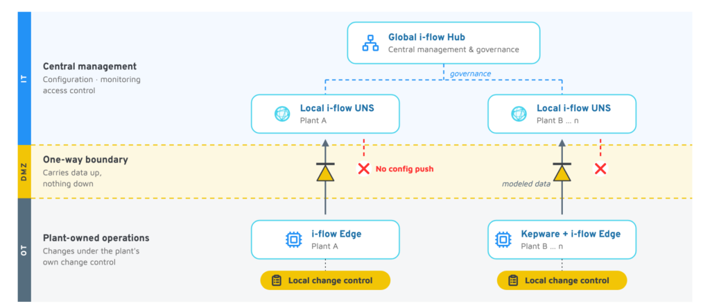
The i-flow Hub at Level 5 provides central management, governance and monitoring for every local i-flow UNS (the dashed line in the diagram). All governance traffic stays on the IT side of the diode. Nothing in the management plane requires the diode to carry traffic toward production. Because the diode carries no traffic downward, configuration and lifecycle changes to i-flow Edge and Kepware are applied on the OT side under the plant’s own change-control procedures.
Publish once, consume everywhere
Because consumers subscribe to the UNS instead of connecting to machines, a new dashboard, model or business system is added on the IT side. Neither the plant floor nor the diode configuration has to change.
Implementing the Architecture in 8 Steps
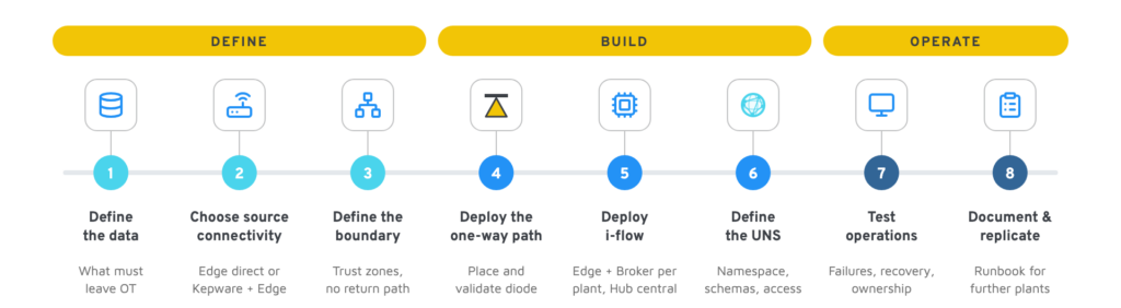
The following framework turns the reference architecture into a project plan. It starts with the data that must leave OT and ends with a documented pattern for further plants:
- Define the data: Identify the production data sources and define exactly which business information must leave OT.
- Choose the source connectivity: Decide per plant whether i-flow Edge connects the sources directly or whether an existing Kepware layer feeds i-flow Edge.
- Define the boundary: Define the source and destination trust zones and the OT/IT security boundary. Confirm that the use case does not require a reverse communication path.
- Deploy the one-way path: Place the ArrowLinx Data Diode at the OT/IT boundary and validate the one-way data path.
- Deploy i-flow: Deploy i-flow Edge and i-flow Broker in every plant, connect the brokers to the NATS Supercluster and set up i-flow Hub centrally.
- Define the UNS: Define the namespace structure, schemas, access policies and downstream subscriptions in i-flow.
- Test operations: Test failure modes, data integrity, monitoring, availability, recovery and operational ownership. Apply defense-in-depth controls around the overall architecture.
- Document and replicate: Document the reference architecture and the operational runbook for future sites and lines.
The data diode remains one layer within a broader security concept. Our article on secure UNS architectures describes the further measures that belong to it.
Conclusion: One Repeatable Pattern for Every Plant
The data diode reference architecture combines a modern industrial data foundation with a clearly defined and enforceable security boundary. i-flow provides connectivity, edge processing, contextualization, messaging and central UNS governance. ArrowLinx provides a hardware-enforced one-way path for scenarios where production data needs to move outward but inbound connectivity is neither required nor desirable. The pattern fits security-sensitive sectors where one-way OT data export is especially valuable: critical manufacturing, energy, pharmaceuticals, food and beverage, and automotive.
Three key takeaways
- One architecture for two starting points: Plants connect their sources directly through i-flow Edge or keep Kepware where it is already in place or where its drivers are needed. In both cases, i-flow Edge models the data on the OT side.
- Data flows up, never down: Six clearly owned stages move data from the machine to the global UNS. Governance stays on the IT side, and OT-side changes follow the plant’s own change control.
- Repeatable from Plant A to Plant n: Each new site adds i-flow Edge, one data diode and one local UNS. It adds data to the global backbone, not new integrations.
About Allied Solutions: Allied Solutions (Allied Solutions Pte Ltd) is an industrial automation, digital manufacturing and OT cybersecurity company headquartered in Singapore, with offices in Vietnam, Malaysia and China. At the core of its OT cybersecurity portfolio is the ArrowLinx Data Diode, a hardware-enforced unidirectional gateway certified to Common Criteria EAL4+. With more than 25 years of experience in industrial environments, the company helps manufacturers, utilities and critical infrastructure operators modernise their operations securely, from industrial data connectivity, MES and industrial analytics to the protection of the OT networks that run them.