
In the modern factory, the combination of Modbus and MQTT plays an important role in the seamless integration of OT and IT systems. Modbus is known for its robustness and reliability in industrial communication environments. MQTT, on the other hand, provides the event-based and scalable interface between OT and IT. In view of the widespread use of Modbus in the industry and the increasing use of MQTT, the need to seamlessly integrate both technologies is growing. In addition, integration within the Industrial Unified Namespace Architecture is becoming increasingly important. Therefore, the following step-by-step guide describes the process of how to successfully integrate Modbus and MQTT.
What is Modbus?
Modbus, a communication protocol developed by Modicon in 1979, is widely used in industrial automation. It simplifies the integration of a wide range of devices such as control systems and sensors within a network. Thanks to its simplicity and robustness, Modbus is ideal for reliable data transmission.
Master-Slave Architecture
Modbus works according to the master-slave principle, whereby the master is the device that sends commands and the slaves are the devices that receive and execute these commands. This structure enables efficient and controlled data communication within networks. Modbus supports various transmission modes, including RS-232 and RS-485 for serial connections and TCP/IP for Ethernet-based connections. This flexibility allows Modbus to function effectively in both legacy and modern industrial network environments.
Storage and Registers
The memory in Modbus is structured into four main types: Coils, Discrete Inputs, Input Registers and Holding Registers. Each type has specific functions and access rights that allow either read-only access or read and write access. Correct addressing within these memory areas is critical to the operation of Modbus networks, as each area uses a unique address and specific operations.
- Coils are binary output positions that can be both read and written and are often used to control relays or switches.
- Discrete inputs are binary inputs that can only be read and record statuses such as sensor values or switch positions.
- Input registers typically store analog inputs such as temperature or pressure measurements and are read-only.
- Holding registers, which are both readable and writable, are ideal for storing configuration data or working parameters that can be adjusted during operation.
Functions and Commands
Modbus defines a series of function codes that are used to read or write memory areas. These codes enable the master to send specific commands to the slaves to read certain data or execute control commands. The implementation and use of these function codes must be precise to ensure the integrity and efficiency of the network. Examples of frequently used function codes:
- Read Coils (Function Code 01)
- Application: Querying the status of several coils in a slave device.
- Example: A master sends a request to read the status of 10 coils from address 20. The slave responds with the current status of these coils, for example 0 (off) or 1 (on).
- Read Discrete Inputs (Function Code 02)
- Application: Querying the status of inputs that cannot be changed by the master.
- Example: The master queries the states of 5 discrete inputs from address 30. The slave sends back the states of these inputs.
- Write single Coils (Function Code 05)
- Application: Control of a specific coil to switch it on or off.
- Example: The master sends a command to set the coil at address 45 to “On”. The slave executes this command and confirms the action.
- Write multiple Coils (Function Code 15)
- Application: Simultaneous changing of several coil states.
- Example: The master sends a request to switch on 20 coils from address 50. The slave updates its coils accordingly and confirms the execution.
- Read Holding Registers (Function Code 03)
- Application: Query of register values that can be both read and written.
- Example: The master wants to read the current values of 3 holding registers from address 100. The slave supplies the requested data.
Gateway – the Bridge between Modbus and MQTT
The integration of Modbus and MQTT requires a gateway that acts as a translator between the protocols. The gateway writes or reads Modbus coils and registers and converts them into MQTT messages.

Make sure that your gateway natively supports Modbus and MQTT protocols. Check compatibility with other relevant systems (e.g. control systems, ERP) in your OT/IT landscape. Also, the gateway should offer the necessary security features and, depending on the use-case, meet additional requirements such as redundancy and scalability.
Step-by-Step Guide to Integrate Modbus and MQTT
The following steps must be completed in order to connect Modbus devices to an MQTT broker using a gateway.
Step 1: Check the Prerequisites
Check the existing infrastructure and configure the necessary access rights to ensure reliable integration of Modbus.
Check infrastructure: Check that the Modbus devices and the MQTT Broker are fully functional and set up a test environment. This allows you to test the integration and subsequent adjustments in a controlled environment before making changes in the production environment.
Configure the network: Make the necessary adjustments to your network topology. This includes the configuration of ports and firewalls to enable communication between the Modbus devices and the MQTT Broker while preventing unauthorized access.
Access and authorizations: Make sure that you have access to the Modbus devices, the MQTT broker and the gateway. This also includes the necessary user rights and authorizations to be able to carry out configurations. If necessary, install the corresponding configuration software for the systems.
Step 2: Identify relevant Modbus Registers
Check your Modbus devices to ensure that they reliably provide the relevant data points (registers). This includes identifying the relevant registers in the devices for the use case.
Identify Modbus registers: Determine which Modbus registers (data points such as sensor data, status information) are relevant for your use-case. These include coils, discrete inputs, input registers and holding registers, depending on whether you need writeable control commands or readable sensor values.
Check register types and attributes: Check whether the correct types and attributes have been assigned to the registers. Pay attention to the register addresses, data length and access rights. Make sure that these are configured correctly in the Modbus devices to ensure error-free communication and data processing.
Step 3: Definition of the MQTT Namespace
In Modbus systems, data is communicated via registers that are defined in the device configuration. In contrast, the MQTT namespace is created in collaboration between publisher and subscriber. Adherence to a standardized structure is crucial for effective communication and data organization in MQTT. This step includes:
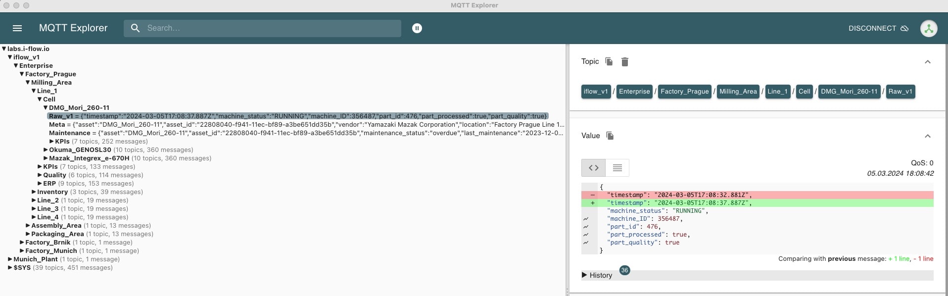
Standardization of the MQTT topic hierarchy: A topic is a UTF-8 string that specifies the path under which a message is published. Clients can publish messages to these topics or subscribe to topics to receive messages. Define guidelines for the naming of these topics, taking best practices into account, to ensure consistency.
Standardization of the MQTT message content (payload): The definition of a standardized payload is essential for interoperability and scalability, especially in the case of a heterogeneous machine park. To do this, create a data model that includes the following components:
- Uniform structure of the payload, including metadata (e.g. machine type and ID) and their representation within the MQTT topics
- Standardized data format, for example JSON or XML, to simplify data processing and integration
- Standardized data types and naming conventions to ensure the uniqueness and comprehensibility of the data.
Step 4: Mapping of Modbus Registers and MQTT Namespace
In this step, you establish a connection between the gateway, the Modbus devices and the MQTT broker. The gateway acts as a bridge between the two protocols and translates Modbus register data into standardized MQTT messages.
Connection test: Check the connectivity between the Modbus devices, the gateway and the MQTT broker. Pay particular attention to compliance with the security guidelines, including the correct setup of authentication and encryption methods.
Mapping of the MQTT payload: Map the relevant data from the Modbus registers to the data model defined in step 3. If necessary, supplement the data model with static inputs (e.g. for metadata such as device type and ID).
Mapping of the MQTT topics: Specify how the MQTT payloads are mapped to the MQTT topics. This can include simple 1:1 mappings or, depending on the requirements of the use-case, require more complex transformations.
Implement transformation logic: Use the functionalities of your gateway to perform the required data conversions. This can include the scaling of measured values, the conversion of data types or the aggregation of data points.

Step 5: Integration of Modbus and MQTT in test environment
Define message transmission: Specify when the Modbus data should be updated in MQTT. The update can take place when changes are made to specific Modbus registers (best practice) or according to a predefined cycle (e.g. every second). You can also define important MQTT settings such as Quality of Service (QoS), Retain and Report by Exception.
Check data integrity: Ensure that the data in your test environment flows correctly from the controller via the gateway to the MQTT broker and that all security mechanisms work as planned.
Step 6: Go-live and Monitoring
Go-live: After successful testing, you can push the Modbus to MQTT integration into production.
Set up monitoring: Implement monitoring and alerting features to continuously monitor system performance and data transmission integrity.
Logging and diagnostics: Ensure that detailed logs are available for troubleshooting and optimizing system performance.
Conclusion
The combination of Modbus devices and MQTT opens up new possibilities for intelligently networked production. Choosing the right integration method is crucial for success. By implementing a sustainable integration strategy, companies can demonstrably increase efficiency, boost productivity and ultimately improve their competitiveness. Standardized mapping of the Modbus registers and the MQTT namespace across systems and factories is a key aspect for successful integration. This can only be achieved via a gateway that supports the standardization and scaling of the MQTT namespace throughout the company.